Marco Mori, Gerardo Masiello, Vincenzo Mamone
SMStrutture, Italy, info@smstrutture.it

The paper illustrates the project for a structural glass walkway that will connect two important historical buildings in Pisa, Palazzo delle Logge di Banchi and Palazzo Pretorio, which are currently used as administrative offices by the City Council. The entire project is developed with particular attention to the conservation of those buildings, the idea is to build a transparent glass footbridge that does not distract people’s attention from the surrounding buildings. The pedestrian walkway has a span of 9.15 metres over the main pedestrian and commercial street of Pisa. In order to combine the demands for both high transparency and fail safe design, the structure will be realised with laminated jumbo glass slabs as main load bearing structure and with joints properly developed to ensure a mutual collaboration of the structural elements. The result of the project will be a complete transparent footbridge with small joints that satisfy both the architectural and the safety requirements.

Keywords: Glass walkway, Glass footbridge, Jumbo glass slabs, Laminated glass slabs, Glass design.

Introduction

The project for a structural glass walkway originates from the plan of the Municipality of Pisa to connect two historical public buildings of the old town centre, respectively Palazzo Pretorio and Palazzo delle Logge di Banchi, see figures 1a) and b). The design, signed by arch. Roberto Pasqualetti, was developed by paying specific attention to the architectural and historical value of these two buildings. The basic idea is to build a footbridge that does not alter the Renaissance perspective of this area.

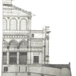
Fig. 1a) Artist impression of the glass walkway between Palazzo delle Logge di Banchi (centre) and Palazzo Pretorio (left), b) site plan.

The pedestrian walkway spans a distance of 9.15 metres overt the main pedestrian and commercial street of Pisa. For this reason, the design of the glass footbridge has to guarantee the safety requirements according to the basic concept of fail safe. In order to combine the demands for high transparency and fail safe design, the structure is made of continuous laminated jumbo glass slabs with metal mechanical joints that guarantee the structural hierarchy, robustness and redundancy in case of an unforeseen breakage of a glass layer of any laminated element. The joints are developed in order to achieve a global structural response of all the glass elements and an efficient behaviour for all load conditions.
The solution proposed does not involve the use of glass fins or other stiffening frames, thus obtaining a more transparent structure.

System description

The footbridge is designed to join the first floor of Palazzo delle Logge di Banchi with the third floor of Palazzo Pretorio at a height of 12.6 m from the street; it is composed of seven laminated glass slabs, see figures 2a) and b). Continuous laminated glass slabs are chosen for lateral and top sides, whereas the bottom slab, being more vulnerable to breakage due to the service load is subdivided, into four elements. In this way, in case of breakage of one of the floor panels, it would be replaced rapidly and easily. The lateral and bottom slabs consist of four 12-mm- thick laminated glass layers joined using 1.52 mm interlayers. The top slab is made of three 12-mm-thick laminated glass layers joined using 1.52 mm interlayers.

Fig. 2a) Exploded view and b) cross-section of the glass walkway.
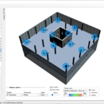
The cross-section of the lateral and bottom glass slabs is symmetrical: the outer glass layers of the lateral slabs are heat strengthened (HSG) and the inner glass layers are thermally toughened (TTG); the outer glass layers of the bottom slabs are made of two thermally toughened (TTG) glass layers and of two inner heat strengthened (HSG) glass layers; the top slab is made of one heat strengthened glass layer (HSG) at the top and two thermally toughened glass layers (TTG) at the bottom.
One of the main design challenges of the project was to increase the out-of-plane stiffness of the vertical glass slabs, which was very low due to their wide free span. At the beginning, the use of “small” slabs connected with longitudinal glass fins and frames was investigated, together with the introduction of diagonal tie rods below the floor level; in a second moment, though, this solution was rejected because it required a large number of connections and reduced the transparency desired.
Later on, a more challenging solution was proposed, to build a glass footbridge made of continuous laminated jumbo glass slabs for the roof and for the load-bearing vertical elements. The post-breakage behaviour of this kind of glass structure strongly depends on the type of glass adopted (annealed, tempered, heat strengthened glass or a combination of them), on the restraint scheme and on the possible association with other materials, e.g. interlayer or metal connections. The laminated glass provides a better breakage behaviour, thanks to the interlayer that holds the splinters, restricts the crack size and offers a good post-breakage load-bearing capacity. On the one hand, the heat strengthened glass (HTG) is better than the thermally toughened one (TTG) since the larger dimension of the splinters enables a better adherence to the interlayer, but on the other hand the tensile strength of the heat strengthened glass is lower than that of the thermally toughened glass. According to the aforementioned considerations, in the glass footbridge both thermally toughened and heath strengthened glass layers will be used.

2.1. Internal and external restraints
The top and bottom slabs are directly connected to the lateral laminated glass slabs by means of stainless steel joints. The lateral slabs are supported at their ends by two steel frames joining the glass footbridge to the masonry walls of the existing buildings.
The global static scheme of the structure is a simply supported beam both in vertical and transversal direction. The external restraints were designed in order to allow vertical and horizontal free motion of the glass walkway without creating unexpected dangerous stresses in the glass in case of earthquakes or settlements of the existing buildings. Figure 3 shows a schematic view of the external bearings.

Fig. 3 Bottom view of the floor slab: global support condition.

To provide the aforementioned static scheme, four different structural bearings have been adopted: the first one is a fixed point restraining any horizontal translation; the second and third ones are multi-direction restraints and allow longitudinal and transversal translations; the last is a one-direction restraint allowing only longitudinal translation. By using this solution the following advantages are reached:

  • the transversal and longitudinal thermal expansions are freely allowed;
  • the relative displacements and rotations of the connected buildings in case of earthquake or differential
    settlement are freely allowed;
  • the footbridge is simply supported in vertical and transversal direction.

2.2. Vertical laminated glass slabs
Lateral laminated glass slabs have a double function: they play as both the principal vertical structural elements and the balustrades. They are simply supported at their ends with a fixed bearing at one end and a sliding bearing at the other one, the glass slabs are connected to the two buildings using steel frames hidden inside the masonry walls.
The laminated glass slabs support their self-weight, the self-weight of the floor and the roof panels, the imposed load, the action of snow and wind. The roof and the floor panels restrain the horizontal displacements of the top and bottom edges of the vertical lateral slabs. It is possible to identify the structure as a statically determinate beam on two supports with a sliding bearing on one side. The floor and roof panels are connected to the vertical glass slabs by means of mechanical joints that do not affect the external glass layers of the vertical slabs.
The glass slabs are 9000 mm long and are made of four 12-mm-thick glass layers joined using 1.52 mm SentryGlas® (SG) interlayers. The outer and inner glass layers are heat strengthened and the two central layers are thermally toughened, because of less impact energy to fracture of the thermally tempered panes (Bos 2009), see Table 1 and figure 4.

Table 1: Composition of the vertical laminated glass slabs.

Fig. 4 Exploded view of the vertical laminated glass slab.

2.3. Floor and roof laminated glass slabs
The floor and the roof carry the imposed load, the snow and the action of the wind and transfer the loads to the main structure by means of the metal point-connections. All the laminated glass panels can be schematised at first approximation as simple-supported plates restrained only at two opposite sides.
The floor and the roof slabs are the main structure of the lateral bearing system for horizontal actions, since they transfer the transversal horizontal load from the lateral laminated glass elements to the end steel frames. In this way, they also provide a mutual collaboration between the lateral jumbo glass slabs and both the floor and the roof slabs.
The floor consists of four identical laminated glass slabs, which are 1960 mm long and 1700 mm wide made of four 12-mm-thick glass layers laminated using 1.52 mm SG interlayer. The top and bottom layers are thermally toughened (TTG) and the two central layers are heat strengthened (HSG), see Table 2. The laminated glass panels have 8 cuts to host the laminated steel plates serving as supports, see figure 5a).

Table 2: Composition of the laminated floor glass slab.

The roof is made of just one laminated jumbo glass slab, 9000 mm long and 2112 mm wide consisting of three 12- mm-thick glass layers joined using 1.52 mm SG interlayer. The top layer is heat strengthened (HSG) and the central and bottom layers are thermally tempered (TTG), see Table 3. Two lines of 11 holes near the longer edges are created in order to connect the top laminated roof to the vertical laminated jumbo glass slabs, see figure 5b).

Table 3: Composition of the laminated roof glass slab.

Fig. 5a) Exploded view of one of the 4 laminated floor slabs, b) exploded view of the laminated roof slab.

2.4. Head steel frame
The lateral, bottom and top slabs, although joined together with multiple point connections, are unstable against twisting deformation. In order to avoid this behaviour, two steel frames will be inserted at the ends of the bridge structure to provide torsional stiffness and to transfer the loads to the support devices and then to the existing buildings, see figure 6.

Fig. 6 Exploded view of the end of the footbridge.

Design

3.1. Loading
The glass walkway footbridge is designed according to Italian building regulations (NTC 08, 2008) and Italian technical recommendations (CNR-DT 210/2013, 2013), which provide a characteristic value of 5.0 kN/m2 as imposed live vertical load on the floor, a characteristic value of 2.00 kN as concentrated vertical load, and a characteristic value of 1.5 kN/m as imposed horizontal load acting on the vertical glass slabs at an height of 1.0 m above the floor.
The characteristic value of the snow load in Pisa is 0.48 kN/m2 but, as the bridge is placed between two higher buildings, a linear snow accumulation was considered on the roof ranging from 1.32 kN/m2 to 0.48 kN/m2 along the longitudinal axis of the footbridge.
The characteristic value of the wind action is 0.753 kN/m2 on the upwind vertical glass slab and is -0.377 kN/m2 on the other downwind glass slabs.
Moreover, the Italian building regulations impose to consider a uniformly distributed maintenance load acting on the roof, having a characteristic value of 0.50 kN/m2. The loads were combined according to the building regulations and Eurocodes UNI EN 1990:2006 and UNI EN 1991-1.

3.2. Glass design challenges
The first step of this study was to understand the structural response of this glass structure. A finite element model of the structure has been implemented in order to investigate the global behaviour of the structure and to calculate the stress state in each glass layer. Furthermore, several sub-models of all slabs and their connections have been created to accurately investigate the local stress state near the mechanical fixings. Various numerical analyses were also performed to investigate the effects of the viscoelastic behaviour of the interlayers; for this reason, different condition of temperature and load duration have been considered.
All numerical models and analyses were made using Strand7® finite element software.
3.3. Global numerical modelling
In the global numerical model the laminated glass panels were modelled using 2D plate elements with effective thickness, while the connections were modelled using beam elements and links, see figures 7a) and b) (Wilson and Vasilchenko-Malishev 2009). This model was used to evaluate the global behaviour and structural response of the entire structure in terms of deflection and reaction forces at the external supports.

Fig. 7a) Isometric view of the global finite element model, b) view of one of the lower connections of the global finite element model.

All 2D plates have two different thicknesses: a membrane thickness that is the sum of the thicknesses of the glass layers for in-plane forces, and an effective bending thickness for out-of-plane forces. The latter is proportional to the elastic modulus of the interlayer and is inversely proportional to load duration and temperature.
In order to evaluate the effective bending thickness of each of the three laminated glass slabs, three different 1000- mm-deep laminated glass slabs were modelled as simply supported at their ends and loaded by a uniformly distributed load. Several numerical analyses with different values of the mechanical properties of the interlayer have been performed and the effective thickness of a monolithic beam has been calculated, see figures 8a) and b). In particular, two different interlayers have been investigated: DG41 and SG.

Fig. 8a) Vertical deflection of a floor glass slab for SLS combination, b) static scheme.

The mechanical response of the laminated glass in ordinary conditions is strongly influenced by the elastic properties of the interlayer that drastically decrease whenever temperature and load duration increase, see figures 9a) and b) (Bennison 2007).

Fig. 9a) Diagram of the principal stresses in the floor slab with SG at the condition T= 10°C and t= 1hr, b) Diagram of the principal stresses in the floor slab with DG41 at the condition T= 30°C and t= 1hr.

Table 4 lists the Young’s modulus of SG and DG41 interlayers for the temperatures of 10°C and 30°C as function of the load duration.

Table 4: Young’s modulus E [MPa] for SG and DG41 interlayers.

Figures 10a) and b) show the diagram of the effective bending thickness of the floor laminated glass slab using DG41 and SG interlayer for the values of temperature of 10°C and 30°C as function of load duration.

Fig. 10a) Variation of effective thickness using SG interlayer as function of temperature and load duration, b) variation of effective thickness using DG41 interlayer as function of temperature and load duration.

In the end, SG interlayer has been chosen for all laminated glass slabs, and a value of 178 MPa for the Young’s modulus and of 0.485 for the Poisson’s ratio has been adopted for a safer design, related to a temperature of 30°C and load duration of one month. The glass was modelled as a linear elastic brittle material responding linearly both in tension and in compression, with a 70 GPa Young’s modulus and a 0.22 Poisson’s ratio. Stainless steel was modelled as a perfect linear-plastic material having a 210 GPa Young’s modulus and a 0.33 Poisson’s ratio.

3.4. Local numerical modelling and design of the connections
The joints have been designed to ensure a structural global response of the footbridge and a proper air circulation inside the walkway to avoid moisture condensation on the glass.
Two types of different connections have been designed: one for glass-to-glass connections and one for glass-to-steel connections. Figures 11 and 12 show the roof connection and the floor connection (Lenk and Lambert 2012; O’Callaghan 2003; Wittenberg and Krynski 2010).

Fig. 11a) Isometric view of the roof connection, b) detail of the connection.

Fig. 12a) Isometric view of the floor connection, b) detail of the connection.

Figures 13a) and b) show the vertical glass slab-to-steel frame connection, which is not laminated but realised with the injection of epoxy.

Fig. 13a) Exploded view of the vertical glass slab-to-steel frame connection, b) detail of the connection

The design of the metal connections has been done by creating detailed local numerical models. 3D solid elements were used to model glass, interlayer, stainless steel and epoxy. The local numerical models were loaded by applying the forces obtained by the results of the global numerical model. In order to evaluate the influences of the time-dependent viscoelastic behaviour of the SG interlayer on the structural response of the laminated elements, different values of the elastic modulus and Poisson’s ratio depending on the action considered were taken into account in the numerical analyses, see Table 5.

Table 5: Value of the Young’s modulus of the SG interlayer.

Fig. 14a) Principal tensile stresses in in the lower glass layer of the laminated floor slab, b) principal tensile stresses in glass at the connection, c) Von Mises stresses in the laminated steel plate of the connection.

Fig. 15a) Principal tensile stresses in in the lower glass layer of the laminated top slab, b) principal tensile stresses in glass at the connection, c)Von Mises stresses in the steel part of the connection.

Fig. 16a) Principal tensile stress in the glass of the vertical glass slab, b) principal tensile stresses in glass at the connection, c) Von Mises stresses in the steel part of the connection.

The tensile stress state generated in glass by each different load has been combined with those generated by the other loads according to the CNR-DT 210/2013. The glass tensile strength, which varies for each load due to the variation of  factor, is obtained from the following formula:

The effect of two or more actions is then evaluated according to the rule proposed by Palmgren-Miner (2) for fatigue damage, where the “partial damage” due to the tension caused by the  load is directly proportional to the ratio between the tensile stress σi and the design tensile strength

3.5. Fail safe design
The fail safe requirements are satisfied trough the hierarchy and the redundancy guaranteed by using laminated panels made of multiple glass layers (Haldimann et al. 2008). Failure of an outer glass layer does not cause the breakage of the other intact glass layers. All the laminated glass panels are accurately designed by assuring that in case of the breakage of a glass layer the other intact glass layers carry the loads safely. A numerical analysis has been performed assuming that the outer glass layer of all laminated glass slabs is broken; in this case, the stiffness of the failed layer is considered to be about 10% of the original value.
3.6. Assembly
The more preferable procedure to construct the glass footbridge is to fix the steel frame to the masonry walls and then place the lateral glass slabs, the glass laminated floor slabs and finally the top laminated glass slab.

Conclusion

The plan to connect two of the more important and historical buildings of the old town centre of Pisa gave us the chance to develop a preliminary project for a fascinating glass footbridge characterised by the use of continuous long laminated glass slabs. The main challenge of the project was to satisfy the architectural demand for high transparency and to achieve the degree of safety required by Italian building regulations. The solution proposed originated from the availability of using continuous laminated jumbo glass slabs reaching length of 9000 mm. So far, we calculated and designed the glass elements and the steel connections; the stresses in glass and in the connections and the calculated deflections widely satisfy the Italian safety requirements.
The design philosophy is based on the concept of fail-safe design; the use of multiple glass layers provides the redundancy and the hierarchy necessary to not impair the whole structure. In case of an unforeseen breakage of a glass layer, the remaining un-cracked layers carry safely all the acting loads.
Particular attention was turned to a detailed design of the external supporting system that has been designed to allow vertical and horizontal motions of the glass walkway without creating unexpected dangerous stresses in the glass elements in case of earthquake or settlements of the buildings.
The project briefly showed in this paper represents a preliminary step of the design activity; several more numerical investigations will be necessary in order to evaluate the exact stress state in glass for all the possible load combinations. A further optimisation of the joints is ongoing in order to reduce the total amount of the connections. Furthermore, a series of experimental tests of both the laminated glass elements and the connections will be provided to investigate their real structural behaviour and to validate the results of the numerical modelling.

References

Bennison S.J.: Designing the Grand Canyon’s new laminated glass walkway. Proceedings of Glass Processing Days 2007, pp. 333-335, Tampere, Finland (2007).
Bos F.P.: Safety Concepts in Structural Glass Engineering: Towards an Integrated Approach. Dissertation TU Delft, ISBN: 987-90-8570-428-7, December 2009.
CNR-DT 210/2013: Istruzioni per la Progettazione, L’esecuzione ed il Controllo di Costruzioni con Elementi Strutturali di Vetro, CNR, Rome, Italy (2013).
Haldimann M., Luible A., Overend M.: Structural Use of Glass, IABSE-AIPC-IVBH, Zurich, Switzerland (2008).
Lenk P., Lambert H.: Challenges in the Design, Fabrication and Installation of Glass Structures Comprising of Super Jumbo Glass Sheets. Proceedings of Challenging Glass 3 – Conference on Architectural and Structural Applications of Glass, IOS Press, pp. 101-110, TU Delft, Delft, The Netherlands (2012).
NTC 08: Norme Tecniche per le Costruzioni, D.M. 14/01/2008, Ministero delle Infrastrutture e dei Trasporti, Rome, Italy (2008).
O’Callaghan J.: Apple Computer Inc Retail Store – All Glass Staircase and Bridge. A Technical Review of Innovative Design and Fabrication Techniques Utilised. Proceedings of Glass Processing Days 2003, pp. 191-194, Tampere, Finland (2003).
Wilson P. Vasilchenko-Malishev G.: Use of laminated glass in a 18m long structural glass walkway. Proceedings of Glass Processing Days 2009, pp. 301-305, Tampere, Finland (2009).
Wittenberg D. Krynski M.: Design of a Single Span Nine Metre Long Glass Bridge. Proceedings of Challenging Glass 2 – Conference on Architectural and Structural Applications of Glass, IOS Press, pp. 227-234, TU Delft, Delft, The Netherlands (2010).